Free ER Diagram Generator
Create professional entity relationship diagrams in seconds. Visualize your database structure with our easy-to-use ER diagram maker—no design skills needed.
Try These Examples
What is an ER Diagram?
An Entity Relationship Diagram, commonly known as an ER diagram or ERD, is a visual representation of how data entities relate to each other within a database system. Think of it as a blueprint that shows the structure of your database before you build it.
ER diagrams use standardized symbols to represent three core components: entities (the objects you're storing data about), attributes (the properties of those entities), and relationships (how entities connect to each other). For example, in an e-commerce database, "Customer" and "Order" would be entities, "customer_name" would be an attribute, and "places" would describe the relationship between a customer and their orders.
Database designers, developers, and business analysts use ER diagrams to plan database structures, communicate system architecture, and identify potential design issues before writing any code. Whether you're building a simple app or designing an enterprise system, an ER diagram helps ensure your data is organized efficiently.
ER Diagram Examples
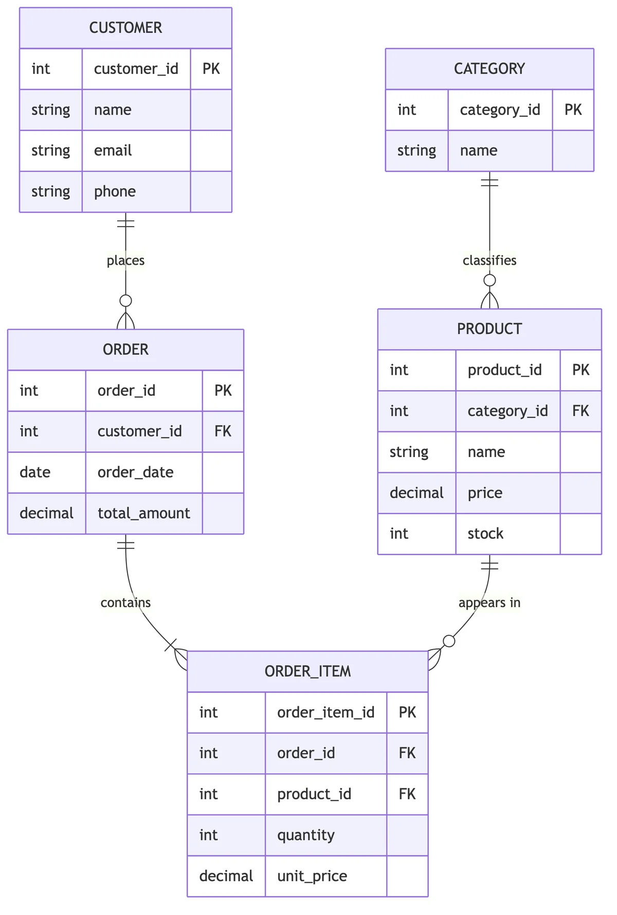
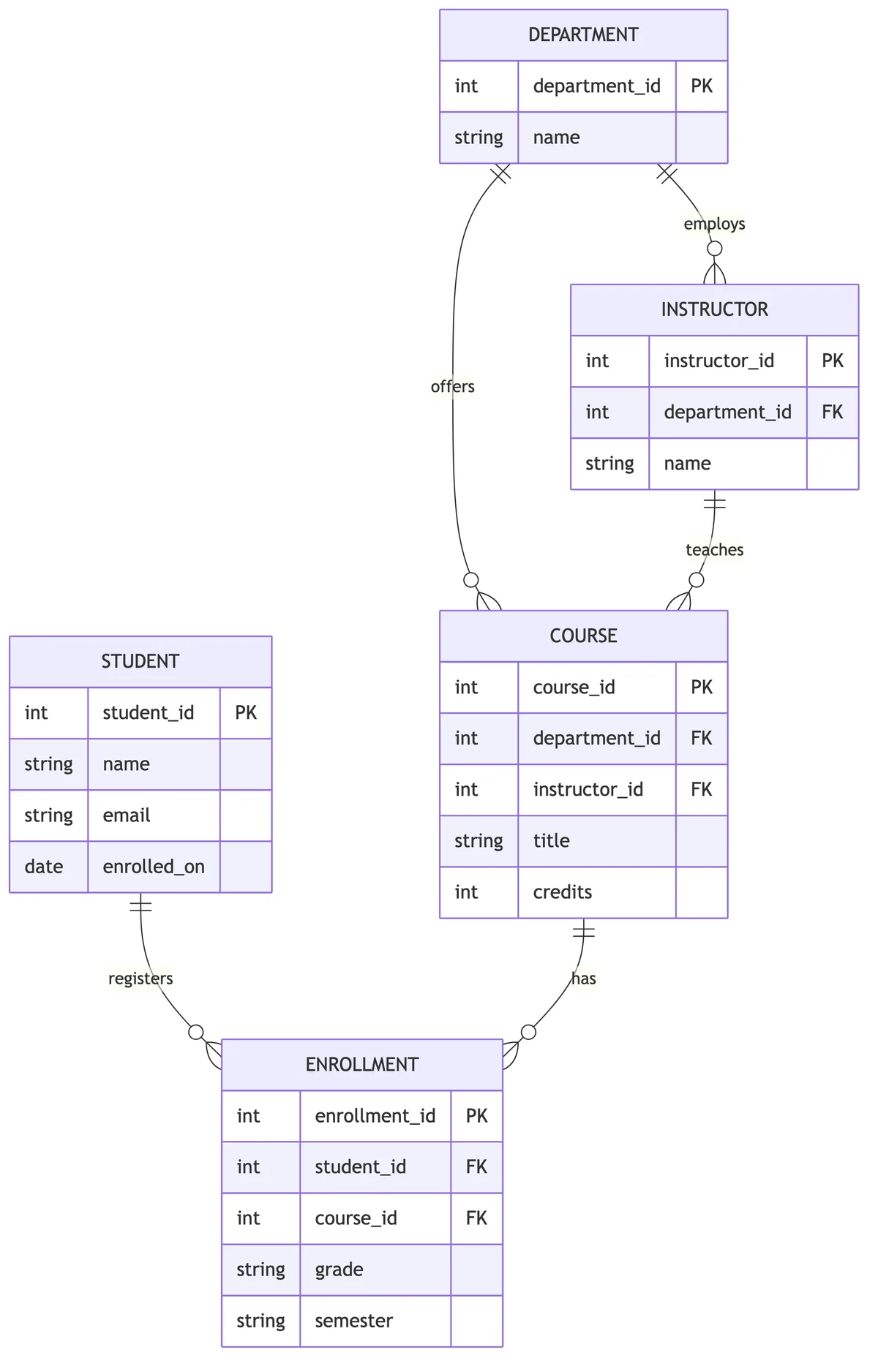
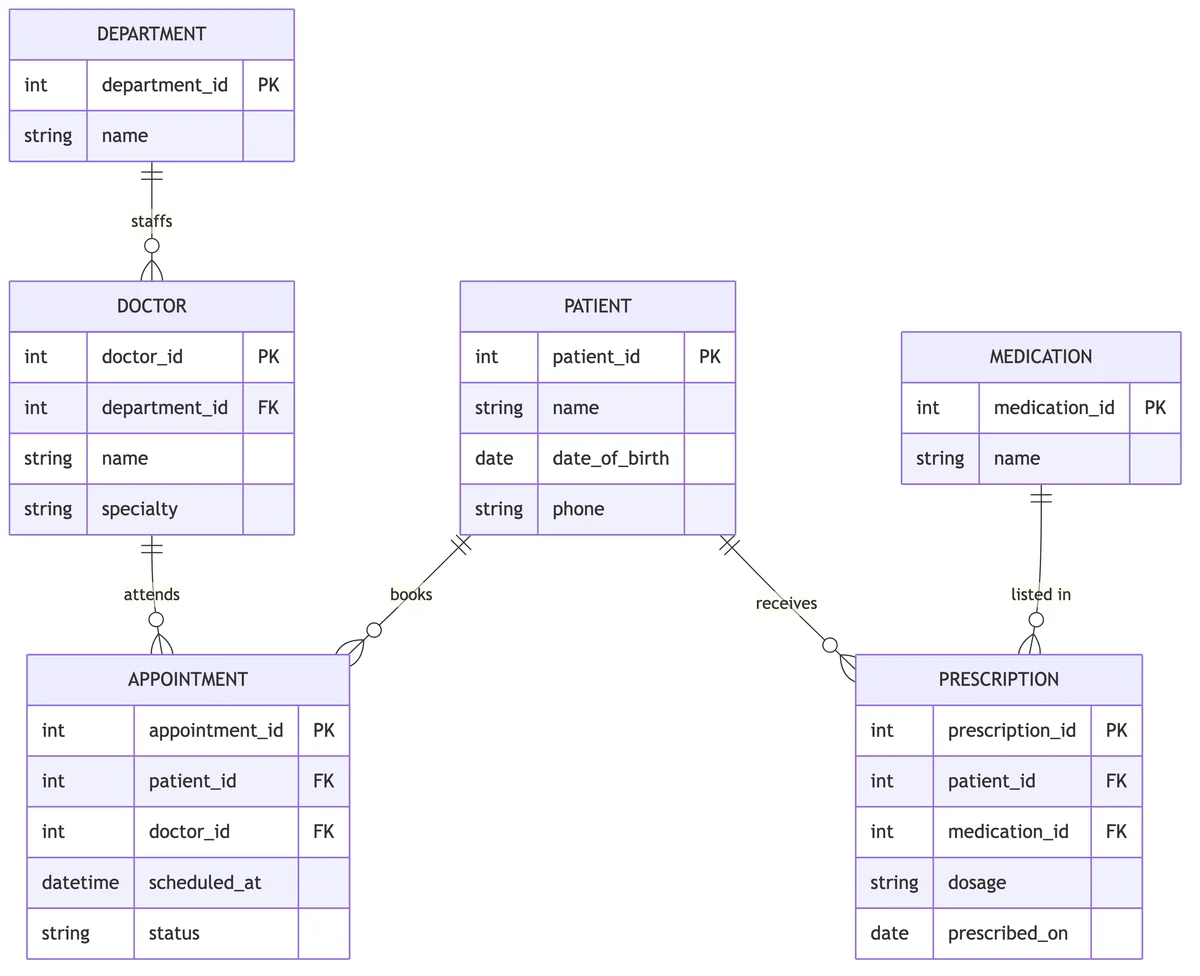
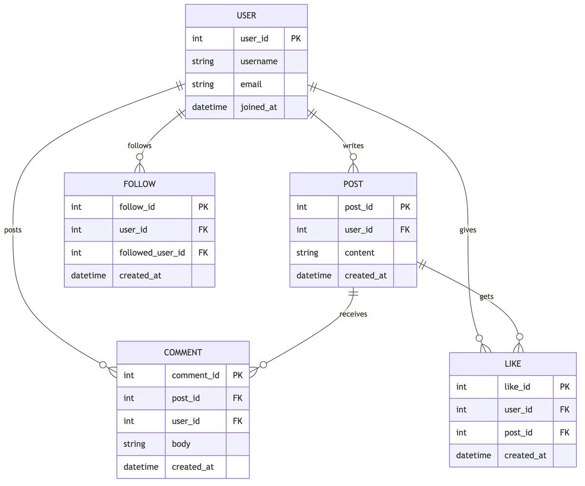
Explore real entity relationship diagram examples across common database designs. Each was generated from a plain-English prompt and shows entities, attributes, primary and foreign keys, and crow's foot cardinality.
How to Create an ER Diagram
Step 1: Identify Your Entities
Start by listing the main objects your database needs to track. These become your entities. For a library system, entities might include Books, Members, Loans, and Authors. Each entity represents a table in your database.
Step 2: Define Attributes
For each entity, identify the properties you need to store. A Book entity might have attributes like ISBN, title, publication_date, and page_count. One attribute should serve as the primary key—a unique identifier for each record.
Step 3: Establish Relationships
Determine how your entities connect. A Member "borrows" Books. An Author "writes" Books. Consider the cardinality of each relationship: can one member borrow many books (one-to-many), or can multiple authors write one book (many-to-one)?
Step 4: Add Cardinality Notation
Use standard notation to show relationship types. Common notations include Crow's Foot (lines with crow's feet for "many") and Chen notation (diamonds for relationships). Our generator handles this automatically based on your description.
ER Diagram Symbols and Notation
Understanding ER diagram symbols helps you read and create effective database designs:
Entities (Rectangles)
Entities are represented by rectangles. Strong entities (those with their own primary key) use a single-line rectangle, while weak entities (dependent on another entity) use a double-line rectangle.
Attributes (Ovals)
Attributes appear as ovals connected to their entity. Primary key attributes are typically underlined. Multi-valued attributes (like phone numbers, where one person might have several) use double-lined ovals.
Relationships (Diamonds)
Relationships are shown as diamonds connecting entities. The relationship name (usually a verb) appears inside the diamond. "Customer places Order" or "Student enrolls in Course" are common examples.
Cardinality Notation
Cardinality indicates how many instances of one entity relate to another. The most common notations are Crow's Foot notation, which uses symbols resembling a crow's foot to show "many" relationships, and Chen notation, which uses "1" and "N" or "M" labels near the connecting lines.
Our ER diagram generator automatically applies the appropriate symbols and notation based on your database description, so you don't need to memorize these conventions.
Chen vs Crow's Foot Notation
ER diagrams use different notations to represent entities and relationships. Chen notation is common in academic textbooks, while crow's foot notation dominates in database design tools. Here's how they compare.
| Aspect | Chen Notation | Crow's Foot Notation |
|---|---|---|
| Entity | Rectangle | Rectangle with an attribute list |
| Attribute | Oval connected to the entity | Row inside the entity box |
| Relationship | Diamond between entities | Line connecting the entities |
| Cardinality | Labels such as 1, N, or M | Symbolic endpoints (bar, circle, and 'foot') |
| Best for | Teaching concepts and academic work | Practical database and schema design |
| Tooling | Less common in modern tools | Default in most database tools and this generator |
Generate SQL from your ER Diagram
Once your entity relationship diagram is ready, turn it into a database schema in one click. The tool converts your ER diagram into ANSI SQL CREATE TABLE statements—with primary keys, foreign keys, and column types included.
How to export SQL
- Generate or refine an ER diagram with the free tool above.
- Click the SQL (database) icon in the diagram toolbar.
- A ready-to-run .sql file downloads with a CREATE TABLE statement for every entity.
Worked example: e-commerce schema
CREATE TABLE "CUSTOMER" (
  "customer_id" INTEGER NOT NULL,
  "name" VARCHAR(255),
  "email" VARCHAR(255),
  "phone" VARCHAR(255),
  PRIMARY KEY ("customer_id")
);

CREATE TABLE "ORDER" (
  "order_id" INTEGER NOT NULL,
  "customer_id" INTEGER,
  "order_date" DATE,
  "total_amount" DECIMAL(10,2),
  PRIMARY KEY ("order_id"),
  CONSTRAINT "fk_order_customer" FOREIGN KEY ("customer_id") REFERENCES "CUSTOMER" ("customer_id")
);

CREATE TABLE "ORDER_ITEM" (
  "order_item_id" INTEGER NOT NULL,
  "order_id" INTEGER,
  "product_id" INTEGER,
  "quantity" INTEGER,
  "unit_price" DECIMAL(10,2),
  PRIMARY KEY ("order_item_id"),
  CONSTRAINT "fk_order_item_order" FOREIGN KEY ("order_id") REFERENCES "ORDER" ("order_id"),
  CONSTRAINT "fk_order_item_product" FOREIGN KEY ("product_id") REFERENCES "PRODUCT" ("product_id")
);

CREATE TABLE "PRODUCT" (
  "product_id" INTEGER NOT NULL,
  "category_id" INTEGER,
  "name" VARCHAR(255),
  "price" DECIMAL(10,2),
  "stock" INTEGER,
  PRIMARY KEY ("product_id"),
  CONSTRAINT "fk_product_category" FOREIGN KEY ("category_id") REFERENCES "CATEGORY" ("category_id")
);

CREATE TABLE "CATEGORY" (
  "category_id" INTEGER NOT NULL,
  "name" VARCHAR(255),
  PRIMARY KEY ("category_id")
);The generated SQL is PostgreSQL-compatible ANSI SQL and works as a starting point for MySQL, SQL Server, and SQLite with minor adjustments.
What Can You Create with Our ER Diagram Generator?
Our ER diagram maker adapts to any database design scenario. Here are popular ways people use it:
E-Commerce Databases
Design Online Store Data Structures
Map out the relationships between customers, products, orders, payments, and shipping. E-commerce ER diagrams help you handle complex scenarios like product variations, shopping carts, wish lists, and order history. Essential for building scalable online retail platforms.
School & University Databases
Academic Information Systems
Model student records, course enrollments, faculty assignments, and grade tracking. Educational ER diagrams capture relationships like students enrolling in courses, professors teaching classes, and departments managing programs. Perfect for learning database design concepts.
Healthcare Systems
Patient and Medical Record Management
Design databases for hospitals, clinics, and healthcare providers. Healthcare ER diagrams model patients, doctors, appointments, medical records, prescriptions, and billing. Helps ensure proper data organization for sensitive medical information.
Inventory Management
Track Stock and Supply Chains
Visualize relationships between products, warehouses, suppliers, and orders. Inventory ER diagrams help businesses manage stock levels, track shipments, and optimize supply chain operations. Critical for retail, manufacturing, and logistics.
Social Media Platforms
User Interactions and Content
Model users, posts, comments, likes, followers, and messaging systems. Social media ER diagrams capture complex many-to-many relationships and help design scalable content platforms. Useful for understanding how major platforms structure their data.
Human Resources
Employee and Organizational Data
Design databases for employee records, departments, positions, payroll, and benefits. HR ER diagrams help organizations manage workforce data efficiently and maintain clear reporting structures.
Types of ER Diagrams
ER diagrams come in different levels of detail depending on your needs:
Conceptual ER Diagram
The highest level of abstraction. Shows the main entities and relationships without technical details. Business stakeholders use conceptual ERDs to understand system requirements and validate data models. No attributes or primary keys—just the big picture.
Logical ER Diagram
Adds more detail including attributes, primary keys, and foreign keys. Independent of any specific database technology. Logical ERDs bridge the gap between business requirements and technical implementation. Database designers use these to refine the data model.
Physical ER Diagram
The most detailed level, showing exactly how the database will be implemented. Includes data types, constraints, indexes, and database-specific features. Physical ERDs translate directly into database creation scripts and are used by database administrators.
Our generator produces any level of ER diagram from your description—high-level overviews or detailed schemas with attributes and data types. Modeling subclasses and hierarchies? Try our EER diagram generator.
How it works:
- Simply describe your database in plain English. "I need an ER diagram for a library system with books, members, loans, and authors. Members can borrow multiple books, and books can have multiple authors."
- Our AI interprets your description and generates a complete ER diagram with proper entities, attributes, relationships, and cardinality.
- Download in high resolution (2K/4K) for professional documentation.
Why use AI for ER diagrams:
- Save hours of manual diagramming
- Automatic notation and symbols
- Consistent, professional output
- Export in high resolution (2K/4K)
- Multiple visual styles to match your needs
AI generation uses credits. New users get free trial credits to experience the full capabilities.
Frequently Asked Questions
Explore More Diagram Types
Need a different type of diagram? Our AI can help you create various database and system visualizations:
Ready to Design Your Database?
Stop struggling with complex diagramming tools or spending hours drawing entity boxes manually. Our ER diagram generator transforms your database ideas into professional diagrams in seconds.
No credit card required • Generate your first diagram in under a minute