Free State Diagram Generator
Create state diagrams and state machine diagrams with our free AI tool. Design UML state diagrams, FSM diagrams, Moore and Mealy machines instantly.
Last updated: July 2026
Try These Examples
What is a State Diagram?
A state diagram (also called a state machine diagram or statechart) is a visual representation of all possible states a system can be in and the transitions between those states. Each state represents a condition or situation, and arrows show how the system moves from one state to another based on events or conditions.
State diagrams help you:
- Model behavior — Define how systems respond to events
- Find edge cases — Identify missing transitions and invalid states
- Document logic — Communicate complex behavior to developers and stakeholders
- Design software — Plan UI flows, protocols, and embedded systems
Common in UML modeling, state diagrams are essential for designing anything with distinct modes or phases—from vending machines to authentication flows.
Types of State Diagrams
UML State Diagrams
The standard notation for modeling object behavior in software engineering. UML state diagrams show states as rounded rectangles, transitions as arrows, and include initial/final states, guards, and actions.
Finite State Machine (FSM) Diagrams
Used in computer science and digital logic design. FSM diagrams represent systems with a finite number of states, inputs, and deterministic transitions. Common in protocol design and embedded systems.
Moore vs Mealy Machines
Two types of finite state machines:
- Moore machines — Outputs depend only on the current state
- Mealy machines — Outputs depend on current state AND input
Moore machines are simpler to design; Mealy machines often require fewer states.
State Transition Diagrams
A general term for any diagram showing states and transitions. Often used interchangeably with state diagram or statechart.
Moore vs Mealy Machines
Both are finite state machines; they differ in how outputs are produced. This is a classic exam and interview question.
| Aspect | Moore Machine | Mealy Machine |
|---|---|---|
| Output depends on | Current state only | Current state and input |
| Output timing | Changes with the state | Can change immediately on input |
| Reaction speed | One clock cycle later | Same cycle (faster) |
| States needed | Often more states | Usually fewer states |
| Typical use | Traffic lights, counters | Vending machines, protocol handlers |
From Transition Table to Diagram
Engineers often start from a state-transition table. Describe or paste one and the AI renders the matching diagram. Here's a turnstile example:
| Current State | Input | Next State |
|---|---|---|
| Locked | coin | Unlocked |
| Locked | push | Locked |
| Unlocked | push | Locked |
| Unlocked | coin | Unlocked |
Paste a table like this (or describe it in plain English) into the tool above to generate the matching finite state machine diagram.
Common State Diagram Examples
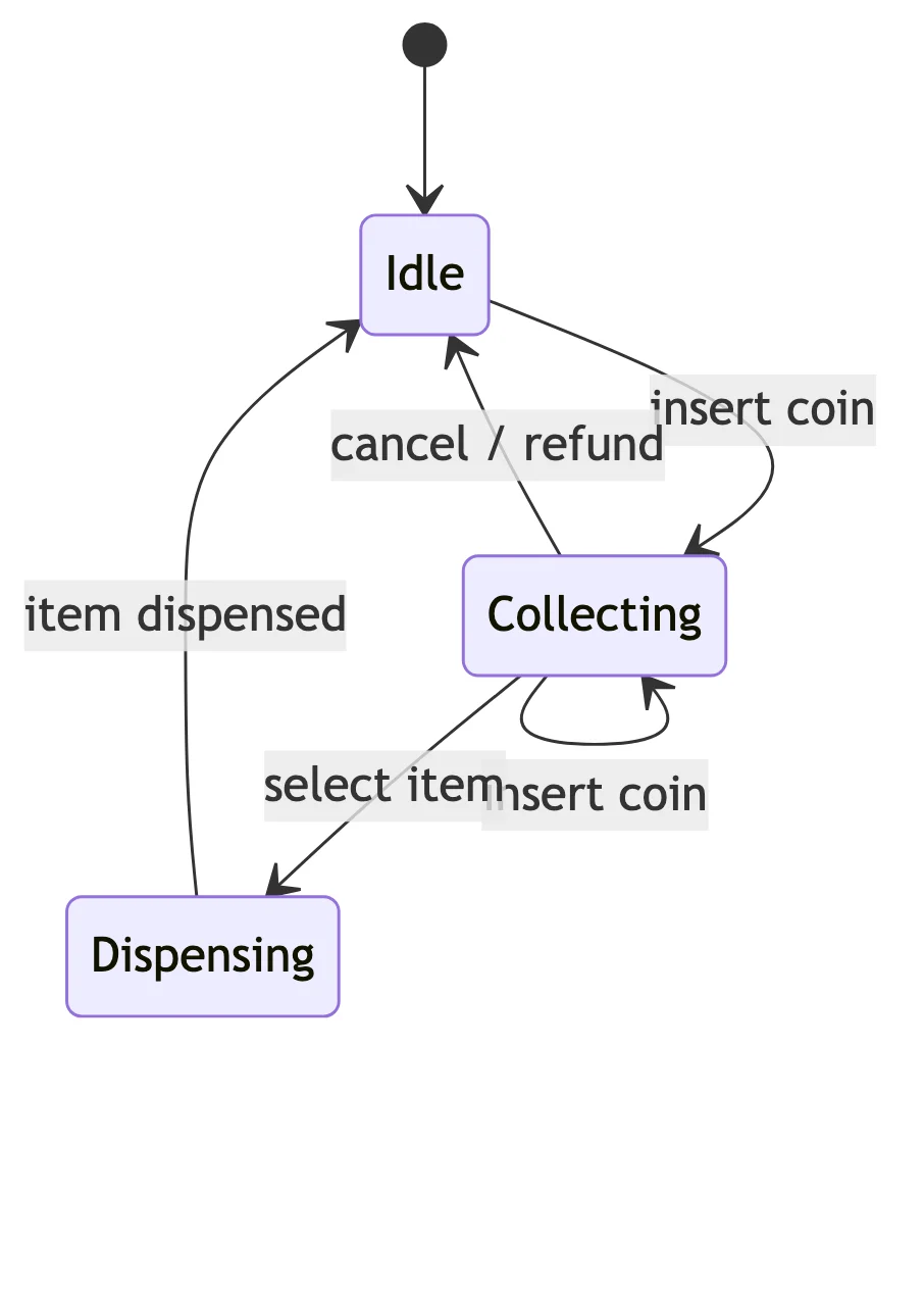
Vending Machine
States: Idle, Accepting Coins, Dispensing, Returning Change. Transitions triggered by coin insertion, product selection, and timeouts.
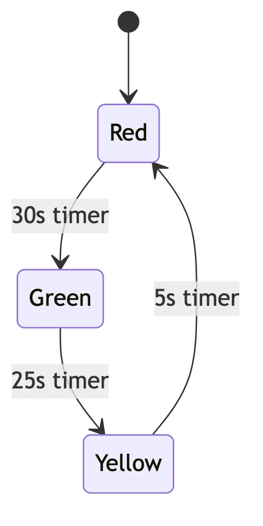
Traffic Light System
States: Green, Yellow, Red (and variations for turn signals). Timer-based transitions with sensor inputs for traffic-responsive systems.
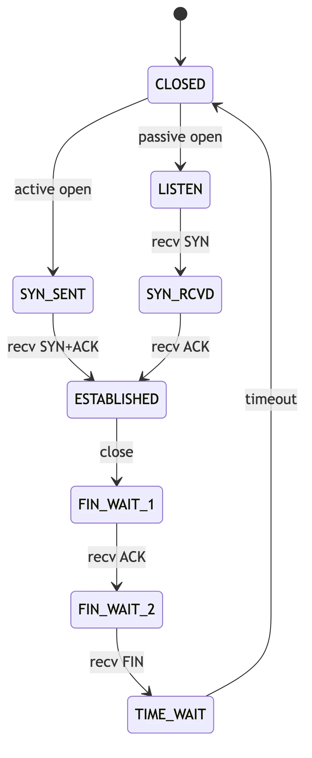
TCP Connection
States: CLOSED, LISTEN, SYN_SENT, ESTABLISHED, FIN_WAIT, TIME_WAIT, and more. The classic example for network protocol state machines.
User Authentication
States: Logged Out, Attempting Login, Authenticated, Session Expired, Locked Out. Transitions based on credentials, timeouts, and failed attempts.
These examples work perfectly with our AI generator—just describe the system and get a complete state diagram.
Finite State Machine Examples
Real FSM and state-diagram examples across hardware and software. Each was generated from a plain-English prompt.
Create State Diagrams with AI
Describe your system's behavior and let AI generate a complete state diagram with all states and transitions.
How it works:
- Describe your system: "State diagram for a door lock with states: Locked, Unlocked, and Alarmed. Correct code unlocks, wrong code three times triggers alarm."
- AI generates the state machine with proper notation
- Download in high resolution for documentation
Works for any state machine:
- Software UI flows
- Protocol designs (TCP, HTTP)
- Embedded systems
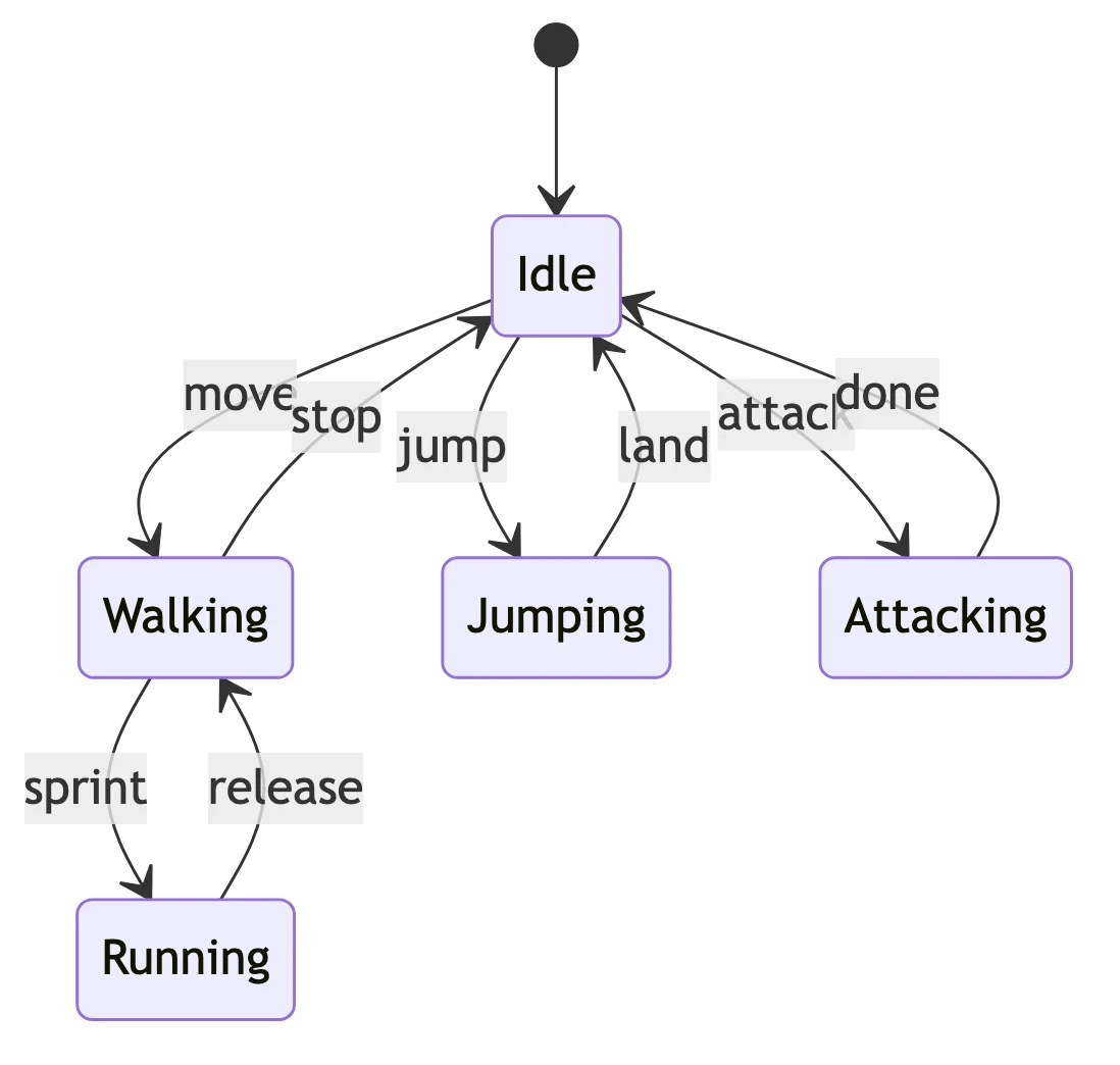
- Game logic
- Business process states
Frequently Asked Questions
Related Diagram Types
Model other parts of your system with these free tools: